© 2022 British Car Club of Charleston. All Rights Reserved.
Drivetrain modifications to Dave Rosato's 1958 MGA
I am doing two modifications to the car. The first is changing the steel wheels to wire wheels. The second is changing the differential drive ratio from the stock 4.3:1 to 3.7:1. This will change the engine rpm at 60mph from about 4000 rpm to about 3450rpm.
Changing from steel to wire wheels
This change requires changing the entire rear axle. The rear axle for steel wheels is about 2" shorter than one for wire wheels. You can buy conversions which simply bolts on a wire wheel hub onto the existing axle. This will move the rear wheels out by about an inch. Years ago I bought a wire wheel rear axle with the intentions of doing the change and never did. Therefore I will use that axle. The differential for the steel and wire wheel axle are the same, so the change to the different axle ratio is being done on the wire wheel axle so the car can still be driven.
Changing the differential drive ratio
There are a few ways to reduce the engine rpm. One is to change the transmission from the standard 4-speed to a 5-speed. The stock 4-speed had a 1:1 ratio in 4th gear. A five speed has a 1:1 drive ratio in 4th gear and a drive ratio, typically, of about 0.82:1 in 5th gear. So if the engine rpm is 4000 at 60mph, it will now be 3280rpm (0.82*4000) in 5th gear. Another way of looking at it, in 5th gear with the engine at 4000rpm, you will now be doing 73mph. Moss Motors sells a conversion for the MGA for about $5,000.
A second way is to add an overdrive. An overdrive is typically a seperate gearbox added behind the existing transmission. They are typically solenoid (electrically) activated. Many British cars were designed to accept an overdrive. (TR6, big Healeys) The MGA was not one of them. The difficulty in adding an overdrive to a car that wasn't designed for one, is first, attaching it to the transmission. Secondly is modifying the drive shaft. There may be structural changes needed to make it fit.
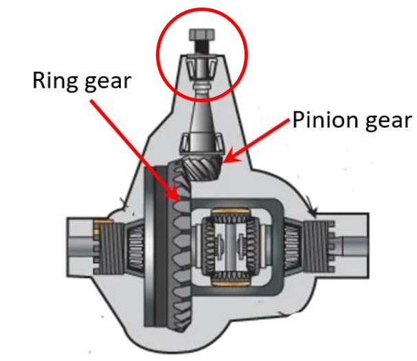
A third way to change the drive ratio, is to change the gears in the differential. The differential is in the rear axle. It changes the rotation from along the car axis to 90 degrees of that, along the axle. In doing so, a ring and pinion gear is used. The number of teeth on the ring and pinion determines the drive ratio of the differential. The stock MGA pinion has 10 teeth and the ring gear has 43 teeth. Therefore the drive ratio is 4.3:1 (43/10). So it takes 4.3 revolutions of the engine to turn the rear wheel one revolution. So if we change the number of teeth on the ring and pinion, we can change the drive ratio. Moss Motors sells ring and pinion gears for 3.9:1 and 3.7:1. I bought gears for 3.7:1. The pinion still has 10 teeth but the ring has 37 teeth. You can't change just the ring gear even though the pinions have the same number of teeth. Ring and pinion gears are machined as matched pairs and cannot be interchanged.
There are a few ways to reduce the engine rpm. One is to change the transmission from the standard 4-speed to a 5-speed. The stock 4-speed had a 1:1 ratio in 4th gear. A five speed has a 1:1 drive ratio in 4th gear and a drive ratio, typically, of about 0.82:1 in 5th gear. So if the engine rpm is 4000 at 60mph, it will now be 3280rpm (0.82*4000) in 5th gear. Another way of looking at it, in 5th gear with the engine at 4000rpm, you will now be doing 73mph. Moss Motors sells a conversion for the MGA for about $5,000.
A second way is to add an overdrive. An overdrive is typically a seperate gearbox added behind the existing transmission. They are typically solenoid (electrically) activated. Many British cars were designed to accept an overdrive. (TR6, big Healeys) The MGA was not one of them. The difficulty in adding an overdrive to a car that wasn't designed for one, is first, attaching it to the transmission. Secondly is modifying the drive shaft. There may be structural changes needed to make it fit.
A third way to change the drive ratio, is to change the gears in the differential. The differential is in the rear axle. It changes the rotation from along the car axis to 90 degrees of that, along the axle. In doing so, a ring and pinion gear is used. The number of teeth on the ring and pinion determines the drive ratio of the differential. The stock MGA pinion has 10 teeth and the ring gear has 43 teeth. Therefore the drive ratio is 4.3:1 (43/10). So it takes 4.3 revolutions of the engine to turn the rear wheel one revolution. So if we change the number of teeth on the ring and pinion, we can change the drive ratio. Moss Motors sells ring and pinion gears for 3.9:1 and 3.7:1. I bought gears for 3.7:1. The pinion still has 10 teeth but the ring has 37 teeth. You can't change just the ring gear even though the pinions have the same number of teeth. Ring and pinion gears are machined as matched pairs and cannot be interchanged.
Tires
When I bought the MGA it had Michelen XZX tires that were very old. I replaced them with the same size NEXEN tires. Of the original 4 tires I bought, 3 went bad in the first couple years. The steel belts broke and created ripples in the side walls. DON'T BUY NEXEN TIRES. The tire size is 65-15.15 inch diameter and series 65. I decided to replace the tires and bought series 80, 15" tires, series 65 tires are hard to find. Unfortunately, after purchasing them, I measures the perimeter of the 65 series and the 80 series. The 80 series perimeter was 8 inches smaller than the 65 series. Therefore, in one revolution of the series 80 tire you travel 8 inches less. This means at the same speed, the tires need to rotate 8% faster. This completely contradicts my goal of reducing the engine rpm. I bought Vredestein Sprint Classic 165R15 tires from Coker Tire. Anyone want to buy 5 Continental 80 series 15" tires?
When I bought the MGA it had Michelen XZX tires that were very old. I replaced them with the same size NEXEN tires. Of the original 4 tires I bought, 3 went bad in the first couple years. The steel belts broke and created ripples in the side walls. DON'T BUY NEXEN TIRES. The tire size is 65-15.15 inch diameter and series 65. I decided to replace the tires and bought series 80, 15" tires, series 65 tires are hard to find. Unfortunately, after purchasing them, I measures the perimeter of the 65 series and the 80 series. The 80 series perimeter was 8 inches smaller than the 65 series. Therefore, in one revolution of the series 80 tire you travel 8 inches less. This means at the same speed, the tires need to rotate 8% faster. This completely contradicts my goal of reducing the engine rpm. I bought Vredestein Sprint Classic 165R15 tires from Coker Tire. Anyone want to buy 5 Continental 80 series 15" tires?
Back to the differential
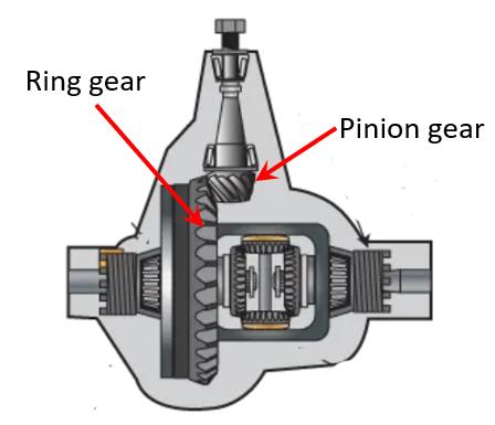
The figure to the right shows the internals of the differential.
I removed the differential from the wire wheel axle. I first removed the bolt inside the hub and then pulled the hub at the rear of the housing, shown below.
The figure to the right shows the internals of the differential.
I removed the differential from the wire wheel axle. I first removed the bolt inside the hub and then pulled the hub at the rear of the housing, shown below.
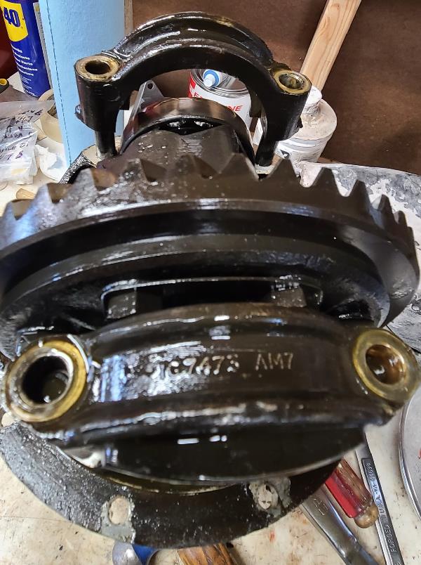
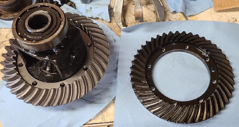
I then removed the four bolts holding the ring gear assemble. I took the picture below so I could put it back together correctly.
I then removed the 8 bolts holding the ring gear in place. The left picture below shows the new ring gear in place. To the right is the original ring gear.
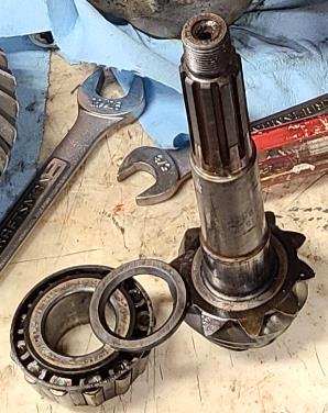
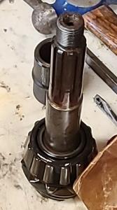
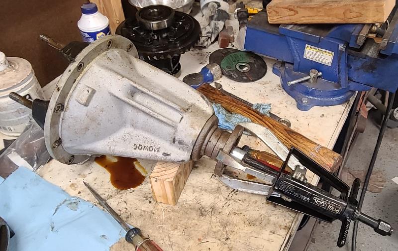
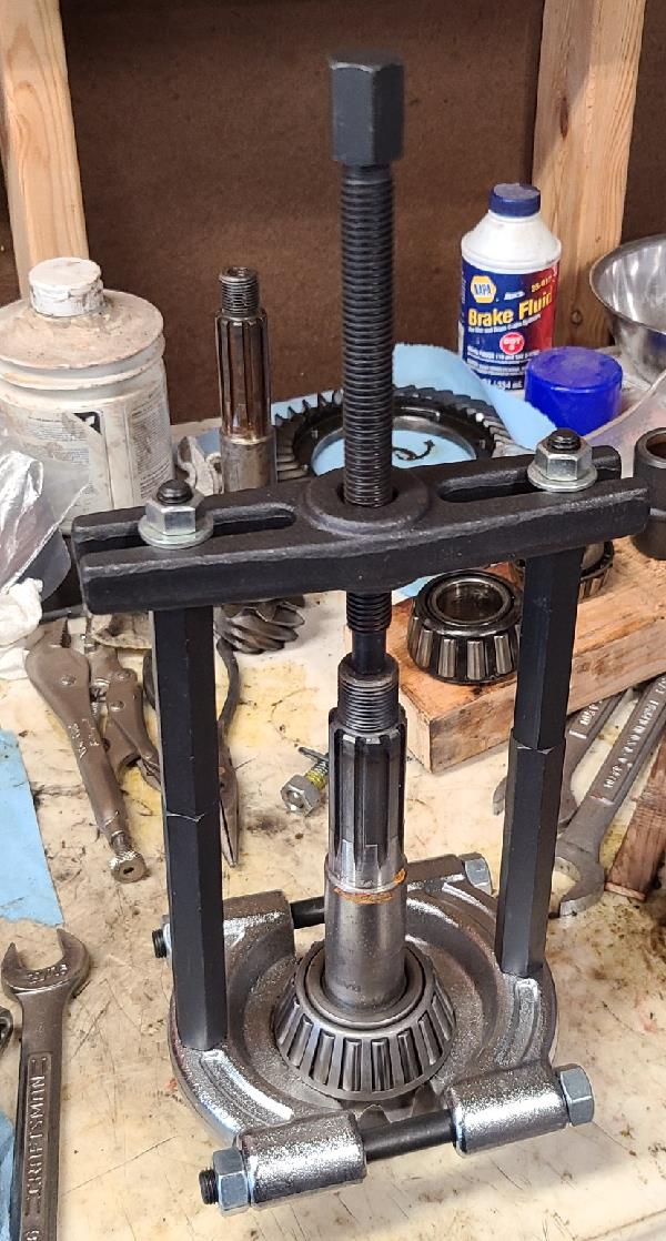
With the ring gear assembly removed, the top of the pinion gear shaft, circled in the picture below, was carefully pounded to release it from the rear bearing. This is shown in the middle picture below. Next the bearing needed to be removed from the pinion shaft. This was a press fit and required a special tool.
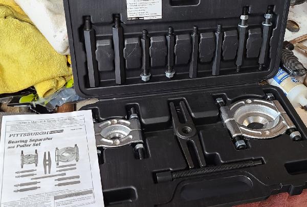
I bought a bearing seperator and puller from Harbor Freight. Part of the tool clamps between the pinion gear and the bearing. Legs are screwed into the clamp and the puller attached to the top, as shown below. The bolt at the top was rotated pulling the bearing up the shaft. It took a propane torch on the bearing to get it freed. There is a shim between the bearing and pinion gear. The picture at the bottom right below shows the removed bearing, the shim and the bearing.
This shim is used to provide the correct mating of the ring and pinion gears. Moss Motors sells this shim in many different thicknesses. I'll talk about how to determine what size shim is needed later. But I used this shim as a starting point for the new pinion gear.
Next I pressed the new pinion bearing on to the new pinion shaft. To make this easier, I put the pinion in our freezer for several hours and the new bearing in the oven set at 450 degrees. The outside diameter of the pinion will reduce in the cold and the inner race of the new bearing will increase in diameter in the heat. I wrapped the pinion and bearing in seperate towels and ran to the garage. I put the shimon the pinion shaft then the bearing. On the bearing a slid on the pinion spacer and a long pipe. Very quickly I pounded the top of the pipe moving the gear down the pinion shaft. This worked out very well.
Next I pressed the new pinion bearing on to the new pinion shaft. To make this easier, I put the pinion in our freezer for several hours and the new bearing in the oven set at 450 degrees. The outside diameter of the pinion will reduce in the cold and the inner race of the new bearing will increase in diameter in the heat. I wrapped the pinion and bearing in seperate towels and ran to the garage. I put the shimon the pinion shaft then the bearing. On the bearing a slid on the pinion spacer and a long pipe. Very quickly I pounded the top of the pipe moving the gear down the pinion shaft. This worked out very well.
I brought the differential housing and new pinion gear outter race to a local auto shop. They removed the old outter race and pressed in the new one. Unfortunately, they also removed the outter race of the rear pinion gear, which hadn't plan on replacing. They couldn't find the outter race so I had to buy a new rear bearing. When it arrived, I heated the housing a bit with a propane torch and pressed in the new outter race.
Shims
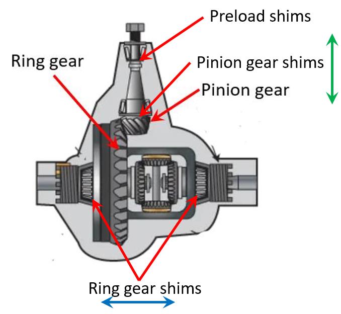
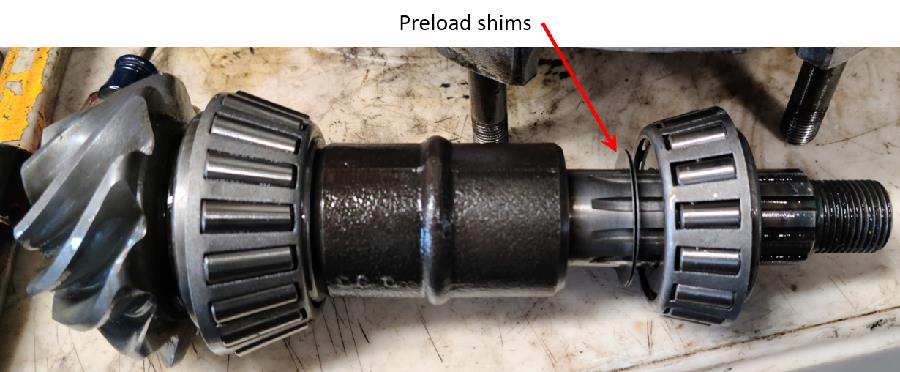
There are three sets of shims in the differential. There are two sets of shims inside of the two ring gear assembly bearings. These shims are used to move the ring gear left and right as shown by the blue arrow in the figure below. As previously mentioned, there is also a shim just behind the pinion gear. This is used to move the pinion gear up and down as shown by the green arrow in the figure below. The preload shims are used to put a defined preload on the two pinion bearings.
There are three sets of shims in the differential. There are two sets of shims inside of the two ring gear assembly bearings. These shims are used to move the ring gear left and right as shown by the blue arrow in the figure below. As previously mentioned, there is also a shim just behind the pinion gear. This is used to move the pinion gear up and down as shown by the green arrow in the figure below. The preload shims are used to put a defined preload on the two pinion bearings.
I dropped the new pinion assembly into the housing. Next I put the new rear bearing on the pinion shaft then put on the rear hub. I put the bolt washer on the shaft then the bolt. I tightened the bolt pressing the rear bearing in place. I didn't use any preload shims. When the bolts was getting near tightened, it got hard to rotate the shaft. Therefore preload shims were needed. I next pulled the bearing just put on the pinion shaft. I added the three shims I had purchased, totaling 0.02". I then put the rear bearing back on. Once again, when the bolt was tightened, the pinion could not be turned. More shims were needed. I once again removed the rear bearing.
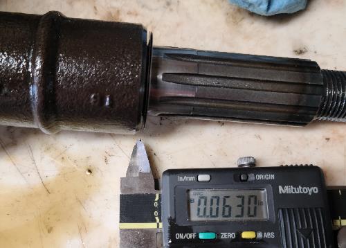
In inspecting the pinion shaft, the preload shims were pressed on the shaft and didn't move. I measured 0.063" gap that needed to be taken up. I ordered more shims from Moss Motors. They won't ship an order less than $10 so I ordered three LED replacement bulbs for under the dash. I'll let you know how that works out.
Surprisingly, the new shims arrived in only a few days. I started by putting 0.08" in shims on the shaft then reassembled it. This time, I could move the pinion shaft in and out by 0.03". I measured this by putting a dial indicator on the housing, supporting the pinion on the bench, then moved the housing up and down. I removed the assembly and removed a 0.03" shim and once again, reassembled it. This time the pinion rotated freely and there was no play.
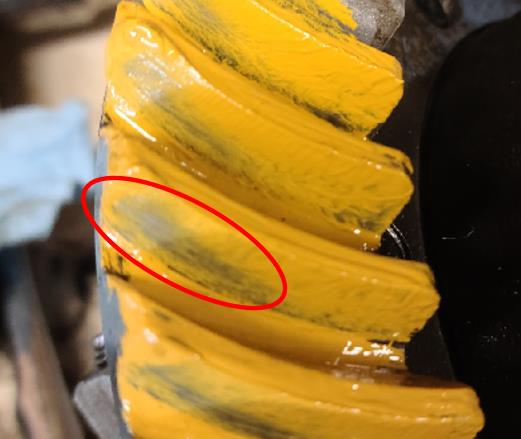
Up to now, I've been using the original shims on the ring gear assembly as well as behind the pinion gear. So far, there is no lateral play in the pinion shaft and there is no play between the pinion and ring gears. But this doesn't guarrantee a good fit. I bought some Gear Marking Compound. This material is used to paint some of the ring gear teeth, shown in the picture below.
Up to now, I've been using the original shims on the ring gear assembly as well as behind the pinion gear. So far, there is no lateral play in the pinion shaft and there is no play between the pinion and ring gears. But this doesn't guarrantee a good fit. I bought some Gear Marking Compound. This material is used to paint some of the ring gear teeth, shown in the picture below.
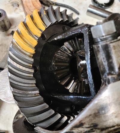
With three or four teeth painted with the material at a couple different locations on the ring gear, hold the pinion shaft to resist rotation slightly and rotate the ring gear several rotations.